First of all, underfloor heating (UFH) is
associated with pipes, insulation and manifolds. Pump-mixing units are not
always remembered. Someone because of misunderstanding how to set up, where to
put, and most importantly why? Someone because of the high cost. However, this
site - the basis of panel heating. Let's look at the options for units that are
on the Ukrainian market.
 |
| Pict.1 Mixing unit of TM-3 FIV |
Functionality
Floor heating is a type of low-temperature
system. For a number of reasons, the water must be supplied to the pipelines
with a temperature below 55 ° C. In our country, "warm floors" are
often combined with radiator heating. The latter works with a heat carrier with
a high temperature (above 55 ° C). This is where the pumping and mixing unit
(MU) finds itself. It produces a decrease in the temperature of the water to
the calculated value for underfloor heating. By mixing two streams - hot (from
the main pipe of the heating system) and cooled (more often from the return
highway after passing the “warm floor” loops).
Consider the scheme of the MU on the example of
the equipment of the German company TECE.
 |
| Pict.2 The scheme of the mixing unit |
The entrance and exit to the main heating system
is located below. Supply line - A, reverse - B. The head regulator is a
thermostatic valve (2) with a thermal head (4). With the help of the latter,
regulation of the supply of hot water to UFH system is carried out. The setting
range is 20 ÷ 55 ° C. Control takes place according to the temperature of the
mixed water that enters the loops of underfloor heating. A remote thermal head
sensor (6) measures it.
The circulation of water in a small circuit
("warm floor") creates a pump (5). The inlet of mixed water to the manifold
(8), the output from the circuits - (9). To remove air in the upper part of the
unit is placed manual air vent (7). The mixing of two streams - the feed from
the heat generator (boiler) (A) and the reverse from the underfloor heating (9)
occurs in the lower left part. A balancing valve (3) regulates the amount of
cooled water entering the mix.
Approximately according to this scheme, all
pump-mixing units work.
Kinds
All MUs can be divided into several categories.
Depending on the mounting base of the
circulating pump used:
- for the pump of 130 mm;
- for the pump of 180 mm;
- universal.
Depending on the working body:
- with thermal head;
- with a three-way mixing valve.
By the presence of a bypass line:
- with bypass;
- without bypass.
By thermal power:
- low-power (up to 15 kW);
- high power (more than 15 kW).
By type of input / output main pipes:
- bottom-down;
- with a side occasion, etc.
By design, the groups differ from each other.
However, many products are similar. Therefore, I will show you the range and
divide them into categories. In which will be located similar products.
MU with one-way
connection from below
This includes the MU TECEfloor (art. 77450000)
discussed above. In addition, a complete equivalent - Fluvia MPG-10-B-W from
Uponor. As well as another subtype - FIV TM-3 and AquaHit MU.301.
For all these groups, the inlet and outlet of
the coolant in the high-temperature circuit are located below.
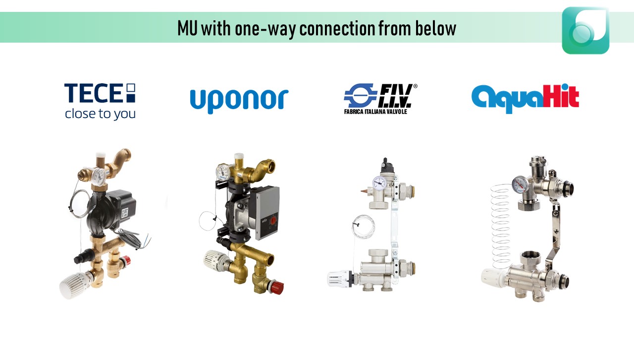 |
| Pict.3 Groups with one-way bottom connection |
Regulation of temperature happens at the
expense of the thermal head. Mixing occurs at the bottom of the group. At the
top is a thermometer. It shows the temperature of the mixed water. Also
installed at the top of the air vent - manual (TECE, Uponor) and automatic
(FIV, AquaHit). Assembly length of the pump - 130 mm. MU of AquaHit has the
ability to also use a 180 mm pump, due to sliding fasteners.
The FIV and AquaHit groups have an integrated
bypass line and plated with a nickel.
The TECE and Uponor groups can adapt to a manifolds
with different center-to-center distances from 206 to 239 mm.
When selecting, it is also important to pay
attention to the maximum thermal power of MU.
 |
| Pict.4 Technical information |
MU with lateral
versatile connection and thermal head
This subtype is one of the most popular in
Ukraine. It is in the assortment of Gross, Sandi Forte, Fado, AquaWorld, etc.
It is obliged to popularity of ease of installation and low cost.
 |
| Pict.5 MU of Fado |
Regulator - thermal head with remote sensor
(1). It is completed with two thermometers, which show the temperature of mixed
water (3) and the temperature of the return line of UFH (6). To prevent the
flow of hot water into the return manifold, a check valve (5) is located inside
the mixing unit.
The group is equipped with a bypass line (4).
It is necessary to protect the pump from overheating in case of overlapping of
all circuits (for example, with actuators). Bypass will pass a small
circulating ring. The amount of water passed into it is adjusted using the
valve (2).
There is an even cheaper modification - without
a bypass.
 |
| Pict. 6 Technical information |
MU with lateral one
way connection
There are the German brands - Watts (ISOTHERM),
Oventrop (Regufloor) and Kermi (xNet Standart). Connection is from the side
(top and bottom). The regulating mechanism is a three-way mixing valve. One of the most compact versions of MU.
 |
| Pict.7 Unit of Watts |
Convenience is the versatility of the
installation - even with the valve down or up. To protect against overheating,
MUs are equipped with an electric overhead regulator. At increase of the
limiting value of the temperature of water for the underfloor heating system -
the sensor switches off the pump. Mixing occurs at the installation site of the
three-way valve. The design
provides a bypass line.
 |
| Pict.8 MU with lateral one-way connection |
To set the temperature of the mixed water, use
the stick (Watts) or thermal head. When you turn the knob on mixing unit Watts
ISOTHERM, the built-in pin clicks when you increase / decrease the value by 1 °
C. The remote sensor from the thermal head is not placed inside the case as in
the previous versions, but is superimposed on top. The maximum power of such
groups is no more than 15 kWt.
 |
| Pict.9 Technicla info |
Combined mixing units
Differ in some complexity of a design, but more
exact hydraulic control. In this category, I put:
- Valtec CombiMix, TechnoMix and ValMix;
- Fado SG21;
- Luxor GM 1192;
- Giacomini R557R-1.
Its beauty lies in the simple connection of two
collector units (main heating system and heated floor) in one group.
 |
| Pict. 10 Combined mix unit |
As can be seen in Figure 10, the MU is located
in the center of the manifolds group. On the left are the high temperature
circuit manifoldss. Through it, the hot water (red line) falls on the MU, where
it mixes with the cooled (blue line). Coming from the loops of panel heating.
Part of the "return" from the warm floor bypass goes immediately to
the return manifold (blue line) of the high-temperature circuit. Mixed water
flows through the low-temperature contour feed manifold (yellow line).
Regulator - thermostatic head. Included are
thermometers, air vent (mostly automatic), drainage taps with fittings (to fill
the floor heating system with heat carrier), mixing valve (2) (pict. 11,
right), bypass control valve (11), ball valves (6) (pict.11, right) (to shut
off the flow and uninstall the pump), etc.
For Giacomini R557R-1, two types of pumps can
be used - 130 and 180 mm. As standard, the kit includes a longer bypass tube.
For the pump 180 mm. It can
be shortened for the second option.
 |
| Pict.11 Operation scheme |
According to the range of MU TM Valtec. The
brand has 3 very similar options - CombiMix, TechnoMix and ValMix. In addition
to the difference in price (listed from the most expensive to the cheapest),
the difference is in the configuration. The last two MUs are completed with one
manual air vent and one drain valve. CombiMix - two automatic air removal and
two drain valves. ValMix is not equipped with a thermal head.
SG21 from Fado - Valtec CombiMix analogue.
Luxor has a slightly different location of the outputs under the manifolds and
the location of the thermal head, but it functions the same.
 |
| Pict.12 Range of combined MUs |
 |
| Pict.13 Technical information |
Separate mixing units
Here it means that the unit consists not of one
integral body, but of several.
 |
| Pict.14 Pump module for floor heating M054 from ICMA |
One part - to connect the circulation pump. The
second is a mixing valve with a thermal head and a bypass line.
In the first part are placed - the valve for
the suppression of air, the connector under the remote temperature sensor,
drain valve, thermometer. They are located on opposite sides of the
low-temperature circuit manifold.
Representatives are ICMA M054 and Valtec
DualMix. Although the same ICMA has several different modifications of this
group - M055 (with a pump); M058 (pump part only, no bypass, versatile bottom
connection); M059 (like M058, only one-way connection is lower), etc.
In my opinion it is not very convenient for
installation - when it is necessary to assemble the MUs from different parts.
Increases installation time. But on the other hand - a large heat output, high
operating temperature and pressure (10 bar).
 |
| Pict.15 Separate MUs |
These mixing units are suitable for pumps with
an installation length of 130 mm.
 |
| Pict.16 Technical information |
Other MUs
There are also many other options that are not
included in my classification, but used in Ukraine. Among these can be
distinguished Herz, Danfoss, Kan-therm. All regulators - thermostatic valve
with thermal head. At Herz, the MU already installed in the manifold. This
shortens the assembly length of the entire group. The bypass made in the form
of a copper pipe.
 |
| Pict.17 Mixing groups Herz, Danfoss, Kan-Therm |
All designed for pump 130y assembly length.
 |
| Pict.18 Technical info |
As a result, I would like to say that it is so
important which pumping and mixing module you choose. It is important that
there is an understanding of why it is needed and how to install it. To
simplify the last point, I post here links to instructions for installing and
configuring different mixing units.
Yes, it will be warm in your home)
Комментарии
Отправить комментарий